电流表电压表+液晶面板电路,Voltmeter + Amme
电流表电压表+液晶面板电路,Voltmeter + Ammeter LCD panel
IntroducTIon
--------------------------------------------------------------------------------
This mulTImeter was designed to measure output voltage and current in a PSU, where the current sense shunt resistor is connected in series with load at the negaTIve voltage rail. It needs only one supply voltage that can be acquired from main PSU. An addiTIonal function of the multimeter is that it can control (switch on and off) an electric fan used to cool the main heatsink. The power threshold at which the fan switches on can be adjusted using One Touch Button Setup.
Technical Specifications
single uC ATMEL ATmega8 used to handle all the multimeter functions.
voltage range 0-30V.
voltage measure resolution 10mV.
current measure resolution 10mA (depended on current sense resistor value).
single, non isolated voltage supply.
one side PCB.
compact construction allowed to use the multimeter as panel meter.
compatibility with standard LCDs based on HD44780 controller.
Schematic
------------------------------------------------------------------------------
Bellow you can see the multimeter schematic. There are some components in the parts list marked as "Do Not Assemble". That components was needed in a previous software edition. Current software version doesn't need them, so you just don't add them. Maybe in a future version of the multimeter there will be a simpler PCB with simpler electronic diagram too.

click image for higher resolution
PCB
--------------------------------------------------------------------------------
PCB files are >here<. There are two version of PCB - normal and mirrored. I think, that anyone who makes PCBs will know which one should be used to produce right PCB.
After soldering all the parts on PCB:
make two cross connection on PCB (see "Layout - bottom side").
short L1 pads.
place U2 element (+12V voltage regulator) on heatsink .
pay attention on right polarity of D1 and D2 elements. Wider side of silk screen layout, where part number is placed, is CATHODE.
Layout - bottom side

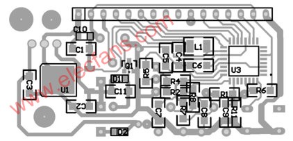
Layout - top side
Parts List
--------------------------------------------------------------------------------
Element Value/Type Case Remarks
R1 100k 1206
R2 100k 1206
R3 10k Potentiometer
R4 30k 1206
R5 10k 1206
R6 10k 1206
R7 7k5 1206
R8 7k5 1206
R9 500R Potentiometer
R10 500R Potentiometer
R11 5k1 1206
C1 100n 1206
C2 100n 1206
C3 100n 1206
C4 100n 1206 Do Not Assemble
C5 100n 1206 Do Not Assemble
C6 100n 1206 Do Not Assemble
C7 100n 1206 Do Not Assemble
C8 100n 1206 Do Not Assemble
C9 100n 1206 Do Not Assemble
C10 22u/6V SMD A
C11 10n 1206 Optional element - protect Q1 against voltage peek after switch off fan. Most of the computer type fans which I tested didn't produce voltage peeks dangerous for Q1
C12 10u/50V
L1 47u 1210 Do Not Assemble - cross PCB pads
D1 DIODE SMD A Optional element - protect Q1 against voltage peek after switch off fan. Most of the computer type fans which I tested didn't produce voltage peeks dangerous for Q1
D2 DIODE SMD A e。g。 SK310A
U1 7805 TO-252 Voltage regulator +5V, e。g。 LM7805
U2 7812 TO220 Voltage regulator +12V, e。g。 LM7812
U3 ATMEGA8 TQFP32
LCD GOLDPIN 1x16
J1 GOLDPIN 1x2 FAN_CON - fan connector
J2 GOLDPIN 1x1 +12V_CON - optional +12V supply connector
J3 GOLDPIN 1x1 +35V_CON - main supply connector
J4 GOLDPIN 1x3 ground and measured signals
S1 SWITCH
Q1 MOSFET N SOT-23 e。g。 BSS-138 (fan current lees than 200mA)
Programming
--------------------------------------------------------------------------------
Because ?C is in TQFP package, we can program it after soldering all components on PCB. After that, programming is quite easy to perform. Programming signals are delivered through LCD connector. To make the programming cable, you can use an old PC HDD cable. Picture of my programming cable is shown here:
Remembered, that during programming, the circuit must be supplied with +5V. Depending on your programmer, supply voltage is provided either by programmer, or from separate power supply unit.
Programming cable connection list
LCD Pin number LCD signal ?C signal/Pin Prog signal
1 GND GND GND
2 VCC VCC VCC
4 RS SCK / PB.5 SCK
5 RW MISO / PB.4 MISO
6 EN MOSI / PB.3 MOSI
10 D3 RESET RESET
Download .hex file
After connecting ?C to prog, you should check, if ?C is "visible" for prog. When everything is fine, you can upload code to ?C. The code is available >here< .It is assumed that ?C is new and works with its internal RC clock at 1MHz. If not, set appropriate fuse bits to achieve above mentioned conditions. In addition Brown-out detector should be turned on by enabling BODEN fuse. Recommended Brown-out Reset Threshold Voltage is 4V.
The next thing to do is to cross LCD soldering pads number 1 and 5. That's necessary to provide ground for LCD RW signal. After all, connect LCD module with the multimeter PCB. It is recommended to use a detachable connector for further expandability e。g。 software upgrading.
Installation in PSU and Regulation
Mount multimeter to PSU according to the diagram below:

Connectors and regulation elements
--------------------------------------------------------------------------------
ELEMENT ACTION
S1 Setup button
When pushing this button the shunt resistor value appears. If the resistor value is known, repeat button pushing until correct value reached. If resistor value is unknown (e。g。 self made resistor), short PSU output by ammeter, set some current by PSU current limit regulator and then, push button, lead to equal current indication on ammeter and multimeter.
After resistor value setup, button must not be pressed for about 5 seconds. The next parameter to set up is fan switch-on power threshold. It is not the real power loosed on output transistor (transistors), because multimeter has information on voltage drop on transistor and driving current. To avoid instability switch-off threshold is automatically set to 20% less than switch-on one.
R9 Fine voltage circuit regulation potentiometer.
To reduce ADC conversion errors like un-linearity, gain factor etc. measuring range is divided into two sub-ranges 0-10V and 10-30V (switch threshold can be between 7-13V depend on sourcing current and elements tolerance).
To regulate fine sub-range connect voltmeter to PSU output, set up voltage at about 9V and turn R9 until voltmeter and multimeter indications are equal.
R10 Coarse voltage circuit regulation potentiometer..
There is over-sampling applied in multimeter software, so measuring resolution is the same in fine and coarse circuit and is 10mV. Because of the reason described above multimeter has two measuring circuits.
To regulate coarse sub-range connect voltmeter to PSU output, set up voltage at about 19V and turn R10 until voltmeter and multimeter indication are equal. (If you posses 4.5 digit voltmeter, you could regulate at voltage 30V)
R3 LCD contrast potentiometer. Turn that potentiometer first, if nothing is visible on LCD.
J1 Fan connector.
Pin no. 1: Fan "+"
Pin no. 2: Fan "-"
J2 +12V
If +12V DC is available in your PSU, connect it to that pin. In that case you shouldn't assemble +12V voltage regulator U2 on PCB.
That solution is convenient for multimeter, because eliminates U2 heating and permit to connect fan and LCD with higher current consumption.
If you haven't got +12V DC in your PSU, left that pin unconnected.
J3 +35V
Rectifier bridge voltage. See U2 element you used data sheet to know about maximum voltage it can work properly. On the other hand the minimum voltage on that pin mustn't drop bellow c.a. 9V, or 6.5V if low drop type U2 and U3 voltage regulators were used.
That pin should be connected even if +12V DC is connected to J2 pin. Voltage from that pin deliver information for fan switching.
J4 Measuring signal connector.
Multimeter is suitable for voltage and current measurement in PSU, where current sense shunt resistor is connected in series with load and is in negative rail.
Pin no.1: voltage measurement U - connect to "+" PSU output, best directly to output terminal;
Pin no.2: current measurement I - connect to "-" PSU output, best directly to output terminal;
Pin no.3: ground - connect to shunt resistor terminal opposite to that connected to "-" PSU output.
LCD LCD connector.
Multimeter works properly with LCD's 1x16 logical controlled as 2x8 (most of LCD's available on the market).
Because of linear voltage regulators used in multimeter, sourcing current is limited. Main current consumption elements are fan and LCD backlight, s
- use LCD with LED backlight (typically current consumption is less than 15mA);
- use low speed, low current fan. Additional advantage of that solution will be silence.
Miscellaneous
--------------------------------------------------------------------------------
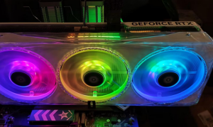
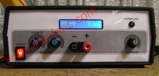
I this picture you can see the multimeter module installed along with 0-30 VDC STABILIZED POWER SUPPLY WITH CURRENT CONTROL 0.002-3A, presented under projects section.
Original design page located here: http://elfly.pl/multimetr/multimetr_en.htm
Warnings
--------------------------------------------------------------------------------
CAUTION
This circuit itself doesn't work off the mains and there are not 220 VAC present, but PSU does.
Voltages above 50 V are DANGEROUS and could even be LETHAL.
In order to avoid accidents that could be fatal to you or members of your family please observe the following rules:
DO NOT work if you are tired or in a hurry, double check every thing before connecting your circuit to the mains and be ready to disconnect it if something looks wrong.
DO NOT touch any part of the circuit when it is under power.
DO NOT leave mains leads exposed. All mains leads should be well insulated.
DO NOT change the fuses with others of higher rating or replace them with wire or aluminium foil.
DO NOT work with wet hands.
If you are wearing a chain, necklace or anything that may be hanging and touch an exposed part of the circuit BE CAREFUL.
ALWAYS use a proper mains lead with the correct plug and earth your circuit properly.
If the case of your project is made of metal make sure that it is properly earthen.
If it is possible use a mains transformer with a 1:1 ratio to isolate your circuit from the mains.
When you are testing a circuit that works off the mains wear shoes with rubber soles, stand on dry non conductive floor and keep one hand in your pocket or behind your back.
If you take all the above precautions you are reducing the risks you are taking to a minimum and this way you are protecting yourself and those around you.
A carefully built and well insulated device does not constitute any danger for its user.
BEWARE: ELECTRICITY CAN KILL IF YOU ARE NOT CAREFUL
- •小尺寸面板价全年跌幅达34%2023-12-28
- •友达本月将关闭新加坡LCD面板生产线2023-12-21
- •刚性OLED面板需求急剧下降 三星显示明年刚性产能消化面临挑战2022-10-10
- •LG 显示计划明年生产 920 万块大尺寸 OLED 面板,近 6 成在广州生产2022-09-27
- •友达:面板拉货趋向积极,整体供需逐步恢复到较平衡状态2022-09-01
- •京东方OLED面板通过苹果新机认证,机构预测至少500万片2022-07-07
- •LG显示将在一年内停止P5车用LCD面板产线运营2022-05-12
- •友达:目前仍无法判定面板报价何时止跌2022-04-22
- •京东方称计划今年将OLED面板交付量提高近70%2022-04-08
- •“面板双雄”回复停电:设备恢复中2022-03-04