
脉宽调制直流电动机控制电路 Pulse Width Modu
来源:电子发烧友 作者:华强电子网 时间:2019-01-22 16:48
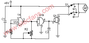
脉宽调制直流电动机控制电路 Pulse Width ModulaTIon DC Motor Control
Often, people attempt to control DC motors with a variable resistor or variable resistor connected to a transistor. While the latter approach works well, it generates heat and hence wastes power. This simple pulse width modulaTIon DC motor control eliminates these problems. It controls the motor speed by driving the motor with short pulses. These pulses vary in duraTIon to change the speed of the motor. The longer the pulses, the faster the motor turns, and vice versa.
SchemaTIc
Parts
|
Part |
Total Qty. |
Description |
Substitutions |
|
R1 |
1 |
1 Meg 1/4W Resistor |
|
|
R2 |
1 |
100K Pot |
|
|
C1 |
1 |
0.1uF 25V Ceramic Disc Capacitor |
|
|
C2 |
1 |
0.01uF 25V Ceramic Disc Capacitor |
|
|
Q1 |
1 |
IRF511 MOSFET |
IRF620 |
|
U1 |
1 |
4011 CMOS NAND Gate |
|
|
S1 |
1 |
DPDT Switch |
|
|
M1 |
1 |
Motor (See Notes) |
|
|
MISC |
1 |
Case, Board, Heatsink, Knob For R2, Socket For U1 |
Notes
1. R2 adjusts the speed of the oscillator and therefore the speed of M1.
2. M1 can be any DC motor that operates from 6V and does not draw more than the maximum current of Q1. The voltage can be increased by connecting the higher voltage to the switch instead of the 6V that powers the oscillator. Be sure not to exceed the power rating of Q1 if you do this.
3. Q1 will need a heatsink.
4. Q1 in the parts list can handle a maximum of 5A. Use the IRF620 for 6A, if you need any higher.
- •使用灯泡的通用电源负载电路2019-01-23
- •电子镇流器电路图2019-01-23
- •USB鼠标电路图2019-01-23
- •主板三相供电和双相供电图2019-01-23
- •自动空气清新器电路2019-01-23
- •一个油炸锅控制电路2019-01-23
- •完整电磁炉电路图32019-01-23
- •完整电磁炉电路图22019-01-23
- •完整电磁炉电路图12019-01-23
- •自动洗手器电路图2019-01-23